Iranian Classification Society Rules

< Previous | Contents | Next >
Section 7 Thermal Containers
701. Application
1. The requirements in this Section apply to the type approval and production unit inspection of con- tainers which are built with insulated walls, doors, floor and roof so as to retard the rate of heat transmission between inside and outside of the container. (hereinafter referred to as "thermal con- tainer")
2. At the request of container owner, type approval, approval of manufacturing process and tests and inspections in respect of refrigerating units and/or heat-producing appliances intended for thermal containers may be carried out by the Society.
702. Materials and workmanship
Requirements for materials and workmanship of thermal containers are as follows in addition to the requirements prescribed in Ch 2, 602.
(1) Proper choice of materials intended for thermal containers and refrigerating units or heating ap-
pliances are to be made so as to produce no harmful effects on cargoes. No damage is to be caused on the materials by carrying out the tests prescribed in 705. 4 and 5.
(2) The quality of insulating materials is to be accepted by the Society.
(3) Insulating work is to be carried out with a scrupulous care.
703. Dimensions and ratings
1. External dimensions and ratings
External dimensions, permissible tolerances and ratings for containers are to comply quirements in Ch 2, 603. 1.
2. Internal length
The minimum internal dimensions of thermal containers are specified in Table 2.6
with the re-
![]()
Table 2.6 Minimum Internal Dimensions of Thermal Containers
Designation | Internal(1) Breadth (m m) | Internal(1) Height (m m) | Internal Length (m m) |
1AAA | 2,511 | 2,218 | 11,502 |
1AA | 2,206 | ||
1A | 2,053 | ||
1BBB | 2,511 | 8,435 | |
1BB | 2,206 | ||
1B | 2,053 | ||
1CC | 2,206 | 5,368 | |
1C | 2,053 | ||
1D | 2,053 | 2,301 | |
1EEE | 2,511 | 13,026 | |
1EE | 2,206 | ||
NOTES: (1) The structure without tunnel recess adds 40 m m to internal breadth of this table. (2) Dimensions of door opening are to be as close as practicable to the internal dimensions of thermal containers. | |||
Ch 2
![]()
704. Design conditions
1. Application
The design conditions to construction and capacity of thermal containers are to comply with the re- quirements in this Section, in addition to those of Ch 2, 604.
2. General
(1) nTohte mcooreefftihciaennt0.4ofWh/emat2℃tr.ansfer (hereinafter referred to as "K") of thermal containers is to be
(2) The maximum heat leakage (U max) and inside and outside design temperatures of thermal con- tainers are specified in Table 2.7.
Table 2.7 Maximum Heat Leakage and Design Temperature of Thermal Containers
Maximum heat leakage U max (W /K ) | Design temperature (℃) | ||||||||
1AAA | 1AA, 1A | 1BBB | 1BB, 1B | 1CC, 1C | 1D | 1EE | 1EEE | Inside | Outside |
42 | 40 | 33 | 31 | 22 | 13 | 44 | 46 | +16 -18 | +45 -20 |
(3) Electrical aspects are to be in accordance with KS A ISO 1496-2 so far as applicable,
3. Insulating construction
(1) The walls, doors, floors and roof of the thermal containers are to be insulated in such a manner as to balance, as far as is practicable, the heat transfer through each of them, although the roof insulation may be increased to compensate for solar radiation.
(2) The structure and the insulation of container are not to be functionally affected by cleaning methods, for example steam cleaning and detergents normally used.
4. Airtightness
Thermal containers are to be of airtight construction and to be complied with the requirements in
705. 3.
5. Refrigerating appliances
(1) Refrigerating units are to comply with following requirements and to have a sufficient capacity taking into consideration the service condition of containers.
(a) Refrigerating units are to have a capacity to run without a hitch and to be capable of effi-
ciently maintaining the specified minimum inside temperature under the test prescribed in
705. 5 (1) (f).
(b) Refrigerating units are also to be capable of efficiently maintaining the specified minimum temperature for a period of at least 4 hours under the test prescribed in 705. 5. (1) (g)
(2) Wcohoelirneg twheatecronfotarinreerfsriguesriantgingofuncitosoliisngtowbaeter36to℃,reafrnidgerthateinsgtruucntuitrse,
prevent from freezing of water.
6. Cooling water connections
itshetodbeseigsno tdeemsipgenreadturaes otof
(1) For appliances requiring water connections, the in-let and outlet interface are to conform to Fig
2.21 and 2.22 and operating and bursting pressure are to be 1 MPa and 4 MPa respectively.
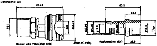
Fig 2.21 Cooling Water Connection-Inlet Side

![]()
Ch 2
Fig 2.22 Cooling Water Connection-Outlet Side
(2) The water inlet and outlet connections are to be located at the machinery end of the container that, to an observer facing that end, they appear in the lower right-hand quarter.
7. Air inlets and outlets
(1) Where 1 AA, 1 CC and 1 C containers are designed for ducted air systems and for use with ex- ternally located removable equipment, the air inlet and outlet openings are to conform to the Fig 2.23 through Fig 2.25 respectively.
(2) Bosses are to be not less than 550 mm diameter or square for 1 AA containers and 457 mm di- ameter or square for 1 CC and 1 C containers.
(3).Holes may have a mould draw taper but no part of the bore of the hole may have a diameter
less than 350 mm in 1 AA containers and 254 mm in 1 CC and 1 C containers.
(4) Faces of bosses are
to be plane to a tolerances of 0.25 mm and are to be parallel to a base
plane determined by front faces of the front corner fittings and recessed 3 to 4.8 mm from this plane.
(5) Closure devices that
the captive to the container are to be provided for closing off the
air cir-
culation openings when the container is not connected to a cold air supply and are to be capable of being sealed for customs requirements.
![]()
Fig 2.23 Air apertures in end wall of 1AA thermal containers
closure
devices

Fig 2.24 Air apertures in end wall of ICC thermal containers
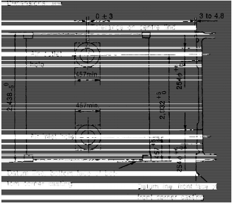
Fig 2.25 Air apertures in end wall of 1C thermal containers
![]()
Ch 2
8. Sanitary structure
The interior surface and structure of the thermal container are to be so constructed as to facilitate cleaning, and adequate provision to be made to ensure that cleaning water can drain satisfactorily from the inside of the container.
9. Drain appliances
(1) Where provision of drains is made on the floor of the container, such drains are to have a
closing device operable from outside the container or arrangement to protect against
intrusion of
water. Further, the drains are to be so constructed as not to worsen the airtightness of the con- tainer remarkably.
Ch 2
![]()
(2) Where cargo space drains are required for cleaning of the interior of the container, they are to be provided with manual closures.
(3) Where operation of cargo space drains is required for the thermal containers when carrying car-
go, the drains are to be protected by fittings which is automatically opened above normal in- ternal operating pressure.
10. Arrangements for hanging cargo
Where on the ceiling of the thermal containers is provided the cargo hanging arrangements, the containers are to be so designed as to be capable of suspending a load of twice the maximum service load or 3,000 kg per meter of the usable container length, whichever is the greater.
11. Temperature measuring device
(1) The suitable instruments are to be provided for measuring the internal temperature of the ther- mal containers, and the temperature is to be measured by automatic temperature records.
(2) Where automatic temperature indicator is used, a suitable calibration.
device is to be provided for its
705. Type Approval Inspection
1. General
(1) The items of type approval inspection for thermal containers
(a) Visual inspection
(b) Dimensional inspection
(c) Mass measurement
(d) Weathertightness
(e) Roof strength test
(f) Airtightness test
(g) Thermal test
(h) Performance test for refrigerating unit
are to comply with the following.
(2) Requirements of tests and inspection prescribed in Ch 2, 605. are also applied in addition to those of this chapter.
(3) Performance tests are to be carried out after successful completion of strength tests.
(4) All instruments and devices used for performance tests are to be properly selected and periodi- cally calibrated by the authorized calibration agencies to the precision as follows;
(a) Temperature measuring devices: ±0.5 ℃
(b) Power measuring system: ±2 % of the quantity measured
(c) Flow meter system: ±3 %
(d) Manometer: ±5 %
(5) The test procedure may be modified as appropriate to cater for special feature of the thermal container and special handling arrangements. In such cases, the general principles outlined herein
are to be maintained.
2. Roof strength test
During the strength test, roof strength test for hanging cargo (where provided is to be carried out as follows.
(1) With the container in the normal position supported at the base corner fittings, a load of twice
the service load or 3,000 kg per meter of the usable container length, whichever is the greater, is to be suspended from the roof support simulating normal service loading.
(2) Maximum deflection and permanent set of the section under test are to be measured.
(3) On completion of the test, container is to show neither permanent deformation nor abnormality which will make it unsuitable for use.
3. Airtightness test
(1) Procedure
(a) The test is to be carried out prior to thermal test after successful completion of all strength test.
(b) The container is to be in its normal operating condition and to be closed in the normal
manner.
(c) Temperatures inside and outside the container are both to be within the range of 15 ℃ to
25 ℃ and temperatures are to be stabilized within 3 ℃ of each other.
Ch 2
![]()
(d) The refrigerating unit/or heating equipment are to be fitted in place, except for the container provided with the removable equipment and having closures at the interfaces. In this case, the equipment is to be removed and the closures are to be shut.
(e) All drain openings are to be closed.
(f) An air supply through a metering device and suitable manometer is to be connected to the container by a leak-proof connection. The manometer is not to be fitted direct to the air
supply pipe.
(g) Air is to be admitted to the container to raise the internal pressure to 250 ± 10 Pa (25 ± 1 mm water head height) and the air supply to be regulated to maintain this pressure. After the steady test conditions are established, the test pressure is to be maintained for not less
than 30 minutes.
(2) Measurements
(a) Internal and ambient temperatures are to be measured.
(b) Air flow required to maintain the test pressure is to be measured.
(3) Requirements
The air leakage rate, expressed in standard atmospheric conditions is to be more than 10 m 3/h. However, for each additional door opening (e.g. side doors) provided, an extra rate of 5 m 3/h is to be granted.
4. Thermal test
(1) Procedure
(A) The test is to be carried out after successful completion of airtightness test.
(B) The test is to be performed with the refrigerating unit and/or heating equipment fitted in
place with all openings closed, except that, where the container is designed for use with re-
(C) The inner heating method only are to be used in the test. The test is to be performed for a period of not less than 8 hours under steady state condition which is maintained following
conditions.
(a) Mean wall temperature is to be in the range of minimum 20 ℃ and maximum 32 ℃,
and a temperature difference between inside and outside not less than 20 ℃.
(b) Maximum temperature difference between any two inside points at any one time 3 ℃.
(c) Maximum temperature difference between any two outside points at any one time 3 ℃.
(d) Mtimaxesim1u.m5 ℃d.ifference
between any two average inside air temperatures, i at different
(e) Mtimaxesim1u.m5 ℃d.ifference
(f) Maximum percentage
between any two average outside air temperatures, e
at different
not to exceed 3 % of difference between lowest and highest power dissipation values is the lowest figure.
(D) The inside and outside temperature-measuring points of containers under the test are to be given in Fig 2.26 and Fig 2.27.
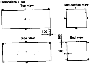
Fig 2.26 Outside Air Temperature Measurement Points
![]()
Ch 2

Fig 2.27 Inside Air Temperature Measurement Points
(E) For the electrical heating method, a non-radiant heater suitably shield and circulating fan(s)
are
are the air
to be positioned at the geometric center of the container and electric heating element(s)
to be operated at temperature sufficiently low to minimize radiation effect. Furthermore heat from the element(s) is to be distributed by a fan or fans delivering a quantity of sufficient, but not exceeding the level necessary, to ensure that the temperature dis-
tribution inside the body of the container is within the limit in (C) above.
(F) Air is to be circulated over the exterior surfaces of the container at a velocity not exceed- ing 2 m/sec at points approximately 100 mm from the mid-length of the side walls and roof
of the container.
(G) All temperature-measuring instruments placed inside and outside the container are to be pro- tected against radiation.
(H) The heat leakage is to be expressed by the total heat leakage rate, the following formula:
![]()
U =
U
which is given by
U : The total heat leakage rate (W/℃)
Q : The power dissipated or absorbed by the operation of internal heaters and fans (W ).
i : The average inside temperature of the container(℃).
e : The average outside temperature of the container (℃).
(I) The mean wall temperature is defined by the following formula.
![]()
=
![]()
(2) Measurements
Data of outside and inside temperatures of the container and power dissipation value are to be taken at intervals of not more than 30 minutes, and the heat leakage U is to be calculated from the average of the 17 or more sets of reading using the following formula and the value of U obtained from this formula is to be recorded together with the mean of the mean wall temper- ature(s) which were maintained during the test period.
![]()
U = U (sets of reading: n ≥ 17)
(3) Requirements
The heat leakage, U, obtained from (2) is to be not more than the value prescribed in 704. 2.
Ch 2
![]()
5. Performance test of refrigerating unit
(1) Procedure
(a) The performance test of refrigerating unit is to be carried out after successful completion of thermal test.
(b) The container fitted with a refrigerating unit is to be placed in a test chamber where the temperature is held constant at the outside temperature prescribed in 704. 2 (2) and the in-
side temperature measured at points specified in Fig 2.27 are not to exceed the specified temperature prescribed in 704. 2 (2)
(c)
(d)
(e)
(f)
(g)
The outside air velocity is not to exceed 2 m/sec at a distance of 100 mm from the side of the container. The inside air velocity is to be produced by the evaporator fans and, fans as-
sociated with heaters.
The test is to be carried out on the container in its normal operating condition. Floor drains, defrost drains (where fitted) and relief valves are to be in their operation states, and doors and vent devices are to be closed in the normal manner.
At this point the unit may be defrosted; if this done, steady-state conditions are to be re-es- tablished prior to continuing the test.
Using the refrigerating unit, the inside temperature of the container is to be cooled down to
-18 ℃ and then maintained this temperature for a period of 8 hours.
After completion of the above-mentioned test, a non-radiant heater placed in the air stream
inside the container is to be turned on, having a capacity of at least 25 % of the total heat transfer rate (U) of the container established by the thermal test prescribed in 705. 4. With the heater in operation, the average internal temperature of the container is to be maintained at the specified inside temperature for a period of at least 4 hours. The capacity of the
heater is defined by the formula below:
Heating Capacity = 0.25 U ( e ― i )
(h) The measuring points of temperature for outside of the container are to be in the place pre-
scribed in Fig 2.26 and for inside of the container the temperatures are to be recorded at least.
(2) Measurements
(a) During the periods of 8 hours and 4 hours of steady-state operation, temperature are to be recorded at intervals not exceeding 30 min.
(b) The power dissipated of electrical heater is to be recorded.
(3) Requirement
It is to be confirmed that the average inside temperature of the container the specified temperature during the test.
at air inlet and outlet
the inside and outside
is to be maintained at
706. Production Unit Inspection for Type-Series Containers
The kinds of tests and inspections for production unit inspection of type-series container are as specified in Ch 2, 403. and to be carried out in accordance with the requirements of 705. and Ch 2, 605.
![]()
Ch 2